Carrier 060 Bedienerhandbuch
Stöbern Sie online oder laden Sie Bedienerhandbuch nach Wärmepumpen Carrier 060 herunter. Carrier 060 Instruction manual [en] Benutzerhandbuch
- Seite / 28
- Inhaltsverzeichnis
- LESEZEICHEN
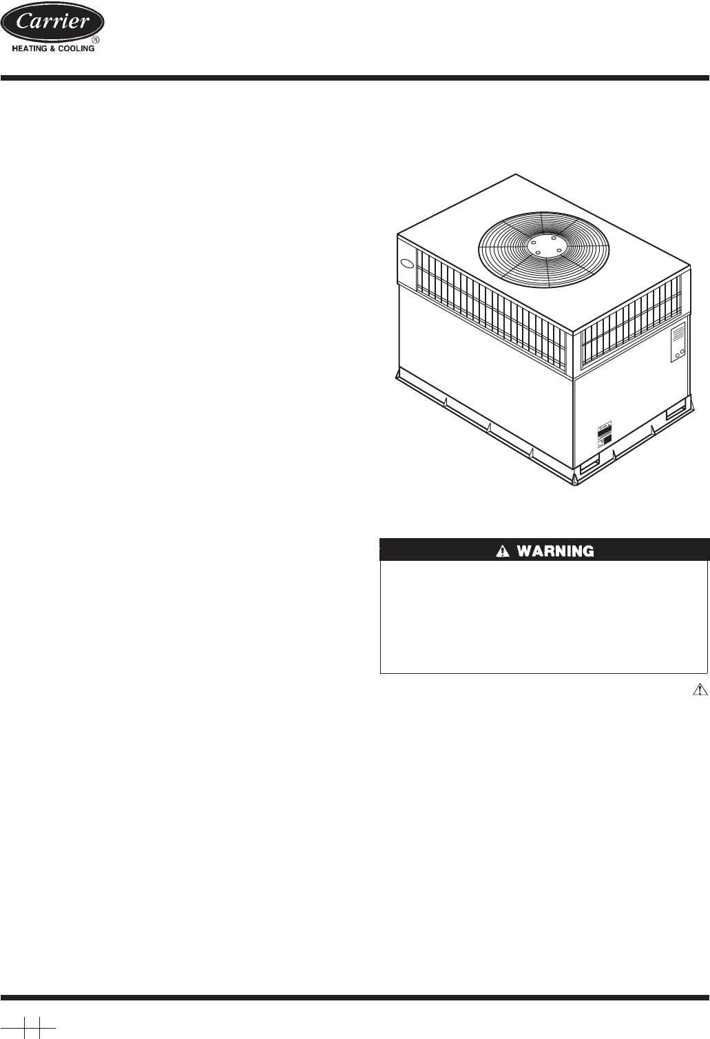
- 50JS,JX018-060 1
- NEC. REQUIRED CLEARANCES 2
- Fig. 4—Roof Curb Dimensions 4
- Fig. 6—Slab Mounting Detail 5
- Fig. 7—Threading Belt 5
- Fig. 8—Suggested Rigging 6
- Table 1A—Physical Data 7
- Table 1B—Physical Data 7
- Fig. 9—Typical Installation 8
- Fig. 11—Condensate Trap 8
- Fig. 12—Wiring Schematics 9
- Fig. 13—Wiring Schematics 10
- Fig. 14—Wiring Schematics 11
- Table 3A—Electrical Data—50JS 12
- 24 V Circuit Breaker 14
- 24 Volt Compartment 14
- Fig. 19—Transformer Label 15
- Fig. 20—Fan Blade Clearance 15
- Fig. 36—Refrigerant Circuit 23
- Fig. 37—Defrost Thermostat 23
- Book 1 4 28
Inhaltsverzeichnis
50JS,JX018-060Single-Package Heat Pump UnitsInstallation, Start-Up and Service InstructionsNOTE: Read the entire instruction manual before starting th
Fig. 13—Wiring SchematicsA00074
Fig. 14—Wiring SchematicsA00075FIELD SPLICETERMINAL (MARKED)TERMINAL (UNMARKED)SPLICESPLICE (MARKED)FACTORY WIRINGFIELD CONTROL WIRINGFIELD POWER WIRI
Table 3A—Electrical Data—50JSUNIT 50JSSIZEV-PH-HZVOLTAGERANGECOMPRESSOR ODFM IDFM ELECTRIC HEAT POWER SUPPLYMin Max RLA LRA FLA FLA Nominal KW* FLA MC
→Table 3B—Electrical Data—50JXUNIT 50JXSIZEV-PH-HZVOLTAGERANGECOMPRESSOR ODFM IDFM ELECTRIC HEAT POWER SUPPLYMin Max RLA LRA FLA FLA Nominal KW* FLA M
be in a conduit until they enter the duct panel; conduit terminationat the duct panel must be watertight. Run the high-voltage leadsthrough the power
SPECIAL PROCEDURES FOR 208-V OPERATION1. Disconnect the yellow primary lead (w110) from the trans-former. See unit wiring label (See Fig. 12 through 1
Fig. 22—Typical Heat Pump Operation, Cooling Mode1. Hot gas from compressor flows through the 4-way valve and is directed to the outdoor coil. It is t
2. Place SYSTEM switch in COOL position and FAN switch inAUTO position. Set control below room temperature. Observethat cooling cycle shuts down when
The charging label and the tables shown refer to system tempera-tures and pressures in cooling mode only. A refrigerant charginglabel is attached to t
INDOOR AIRFLOW AND AIRFLOW ADJUSTMENTSFor heating and cooling operation, the recommended airflowis 350 to 450 cfm for each 12,000 Btuh of rated coolin
UNIT ELECTRICAL CHARACTERISTICSUNIT WEIGHTUNIT HEIGHTIN. [MM]"A"CENTER OF GRAVITYIN. [MM]lb kg X Y Z50JS018 208/230-1-60 283 128.4 37.02 [94
To change the speed of the blower motor (BM), remove the fanmotor speed leg lead from the blower relay (BR). This wire isattached to IGC terminal BM f
Fig. 30—Cooling Charging Chart, 50JX 024 UnitsC99031689 100.030.040.050.060.070.080.090.0207276345414483551620SUCTION LINE PRESSURE (KILOPASCALS)SUCTI
Failure to follow these warnings could result in serious injuryor death:1. Turn off electrical power to the unit before performing anymaintenance or s
exists, be sure that all supply- and return-air grilles are open andfree from obstructions, and that the air filter is clean. Whennecessary, refer to
Table 5—Cooling and Heating Troubleshooting ChartSYMPTOM CAUSE REMEDYCompressor and outdoor fan will not startPower failure Call power companyFuse blo
Cooling and Heating Troubleshooting Chart (cont’d)SYMPTOM CAUSE REMEDYSuction pressure too low (Cool) Dirty air filter Replace filter(Heat) Outdoor co
26
27
Copyright 2000 CARRIER Corp. • 7310 W. Morris St. • Indianapolis, IN 46231 50js1siManufacturer reserves the right to discontinue, or change at any tim
UNIT ELECTRICAL CHARACTERISTICSUNIT WEIGHTUNIT HEIGHTIN. [MM]"A"CENTER OF GRAVITYIN. [MM]lb kg X Y Z50JS048 208/230-1-60, 208/230-3-60, 460-
Before performing service or maintenance operations onsystem, turn off main power to unit. Turn off accessory heaterpower switch if applicable. Electr
INSPECT SHIPMENT — Inspect for shipping damage while unitis still on shipping pallet. If unit appears to be damaged or is tornloose from its anchorage
5. Tighten the tension buckle until it is taut. Lifting bracketsmust be secure in the handholds.6. Attach field-supplied clevis or hook of sufficient
Table 1A—Physical DataUNIT SIZE 50JS018 50JS024 50JS030 50JS036 50JS042 50JS048 50JS060NOMINAL CAPACITY (ton) 1-1/2 2 2-1/2 2-1/2 3-1/2 4 5OPERATING W
The units dispose of condensate through a 3/4 in. NPT femalefitting that exits on the compressor end of the unit. Condensatewater can be drained direc
Fig. 12—Wiring SchematicsA00073FIELD SPLICETERMINAL (MARKED)TERMINAL (UNMARKED)SPLICESPLICE (MARKED)FACTORY WIRINGFIELD CONTROL WIRINGFIELD POWER WIRI
Verwandte Produkte und Handbücher für Wärmepumpen Carrier 060
 (88 Seiten)
(12 Seiten)
(70 Seiten)
(56 Seiten)
(26 Seiten)
(24 Seiten)
(64 Seiten)
(3 Seiten)
(136 Seiten)
(150 Seiten)
(88 Seiten)
(12 Seiten)
(70 Seiten)
(56 Seiten)
(26 Seiten)
(24 Seiten)
(64 Seiten)
(3 Seiten)
(136 Seiten)
(150 Seiten)
© 2020, manymanuals.de. Alle Rechte vorbehalten. | 0.742 s |
 Manymanuals.com
 Manymanuals.de
 Manymanuals.fr
 Manymanuals.it
 Manymanuals.pl
 Manymanuals.cz
 Manymanuals.es
 Manymanuals-pt.com
Kommentare zu diesen Handbüchern